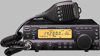
TS-50 USB interface
 The original way to interface a TS-50 transceiver to a computer used to be through a serial interface converter. The serial interface has since been replaced with USB ports. Luckily it is even easier to build a homebrew USB interface for the TS-50!
The circuit
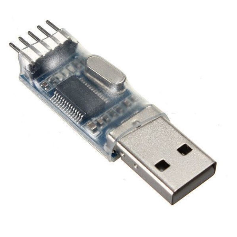
A USB interface for the TS-50 requires nothing more than soldering in a ready-made USB-to-TTL adapter. These can be found on eBay for less than 2 USD.
There’s two different kinds:
- based on the Prolific PL2303HX: these are the cheaper alternative but require drivers to be loaded upon first use, and have poorer OS support.
- based on the FTDI FT232RL chip: these are the more mainstream option. They also provide DTR/CTS signals. Do mind that FTDI drivers have been known to brick devices.
Which version you buy is up to you. Or you can buy both to be sure (the cost won’t kill your budget), so that you can experiment. I am using the PL2303 version which works just fine on my old Windows XP shack computer.
Connecting it to the TS-50
There are a few mounting options for the converter:
- using the TTL-USB converter as the USB plug and bringing in the serial cable. As we’re dealing with TTL level serial data and an HF-rich environment, use properly shielded cable.
- Integrating the converter into the TS-50 and bringing out a USB cable (what I did)
- Integrating the converter into the TS-50 and installing a USB connector in the transceiver. There should be some room to squeeze in a mini-USB socket between the cooling fins on the back.
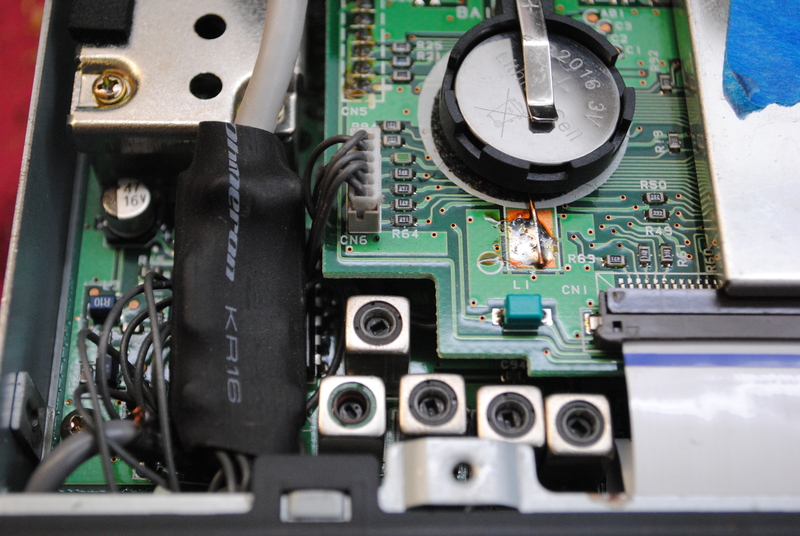
Connecting to the CN6 connector
You will need a connector that mates with the CN6 connector under the patch on the bottom of the transceiver. I stole my connector pigtail from an old VCR, but allegedly the mating connector can be found here:
- CN6 Connector - Digikey: manufacturer JST, part no ZHR-6, description “Conn housing ZH 6pos 1.5mm”
- Pins for connector - Digikey: manufacturer JST, part no SZH-002T-P0.5, description “Conn term crimp ZH 26-28 AWG”
- The HP895 colour printer has the correct pigtail between two boards so it could be scrounged from there.
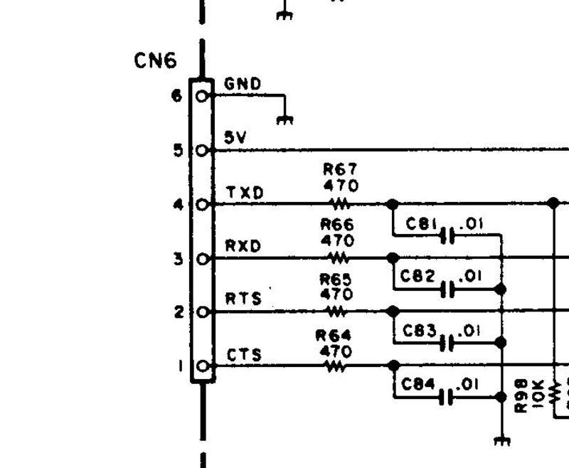
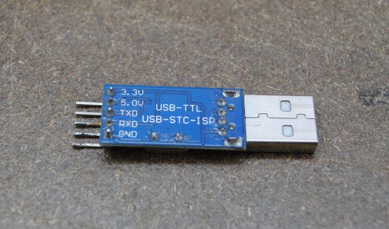
You’ll need to connect the corresponding pins to your USB-TTL converter. This will depend on which unit you bought, so check its datasheet. Here’s the pinout for my PL2303HX-based converter.
WARNING: do not connect the converter’s power pins to the radio (+3.3V or +5V) They are not needed (the converter is powered over USB, and might damage the converter and/or the radio. Only connect GND, TxD and RxD.
I have removed the pin header from the converter, and soldered the corresponding wires from the CN6 connector directly to the pads. I’ve also de-soldered the USB plug and soldered a USB cable directly to the pads. The USB cable exits the transceiver through the patched hole above CN6. The converter was covered in heat shrink tubing.
Testing
When you are troubleshooting the circuit, you might find this info useful:
-
The TS-50’s serial settings are 4800 baud, 1 start bit, 8 data bits, 2 stop bits, no parity, hardware handshaking.
-
Since the Kenwood uses hardware handshaking, the CTS and RTS lines come into play. You can get them out of the troubleshooting process by just looping them (connect RTS to CTS at the radio side, and also connect RTS to CTS at the computer side. Don’t connect them all 4 together!) The circuit will then work fine with just the RxD and TxD signals.
-
A scope with 5 V/DIV and .2mS/DIV will trace the serial signals just fine.
-
The TS-50 outputs a bitstream when you send it a bitstream. I originally tried to send commands on a serial terminal program (Hyperterminal), but got no response. Although this makes no sense to me, I found a terminal program to be useless to try to control the rig. It will work good for troubleshooting using loops though.
-
I used the DOS program RIG-EQF for testing. Other Kenwood-compatible CAT programs should work as well.